Aim
To get familar with Arduino UNO and use it to understand Stepper Motor and it’s basic applications.
Theory
Arduino
Arduino is a programmable ciruit board or mircrocontroller. Which comes with it’s own IDE, called arduino IDE. Arduino helps us connects hardware electronics with logic using simple programming language such as C++. Basically arduino is just a microcontroller that can be operated with your computer using high level programming language. Aruino basically works on the voltage waveforms. But just tweaking the voltage signals we can do a vairety of tasks using arduino.

Stepper Motor
A stepper motor is an electrically powered motor that creates rotation from electrical current driven into the motor. Physically, stepper motors can be large but are often small enough to be driven by current on the order of milliampere. Current pulses are applied to the motor, and this generates discrete rotation of the motor shaft. This is unlike a DC motor that exhibits continuous rotation. Although it is possible to drivea stepper motor in a manner where it has near continuous rotation, doing so requires more finesse of theinput waveform that drives the stepper motor.
Stepper Motor are generally of two types
- Permanent-magnet (PM) stepper motor — This kind of motor creates rotation by using the forces between a permanent magnet and an electromagnet created by electrical current. An interesting characteristic of this motor is that even when it is not powered, the motor exhibits some magnetic resistance to turning.
- Variable-reluctance (VR) stepper motor — Unlike the PM stepper motor, the VR stepper motor does not have a permanent-magnet and creates rotation entirely with electromagnetic forces. This motor does not exhibit magnetic resistance to turning when the motor is not powered.
What is inside a stepper motor? Generally, a stepper motor consists of a stator, a rotor with a shaft, and coil windings. The stator is a surrounding casing that remains stationary and is part of the motor housing, while the rotor is a central shaft within the motor that actually spins during use.
How does a stepper motor work? VR stepper motors work in a very easy to understand manner. The image belwo shows some of the physical details that characterize its operation. In a VR stepper motor, the surrounding coils that are physically located opposite of each other are energized to create opposite magnetic fields. The the image below ,coil C produces a south-pole magnetic field, and coil C produces a north-pole magnetic field. The magnetic fields produced by the coils pass through the air gap and through the metallic rotor. Because the magnetic fields attract each other, the metallic rotor spins in a direction that brings the nearest edges (2 and 4) of the rotor as close as possible to the pair of energized coils (C and C). Like the PM stepper rotor, the VR stepper rotor will remain aligned to the coils as long as coils C and C are energized and the magnetic fields are not changed. To move to the next state and continue this rotation, coils C and C must be deenergized, while coils A and A must be oppositely energized to attract rotor edges 1 and 3 respectively. The same process occurs with coils B and B to attract rotor edges 2 and 4 respectively, and so on.This is an example of a 3-phase VR motor.

Getting Familiar with Arduino
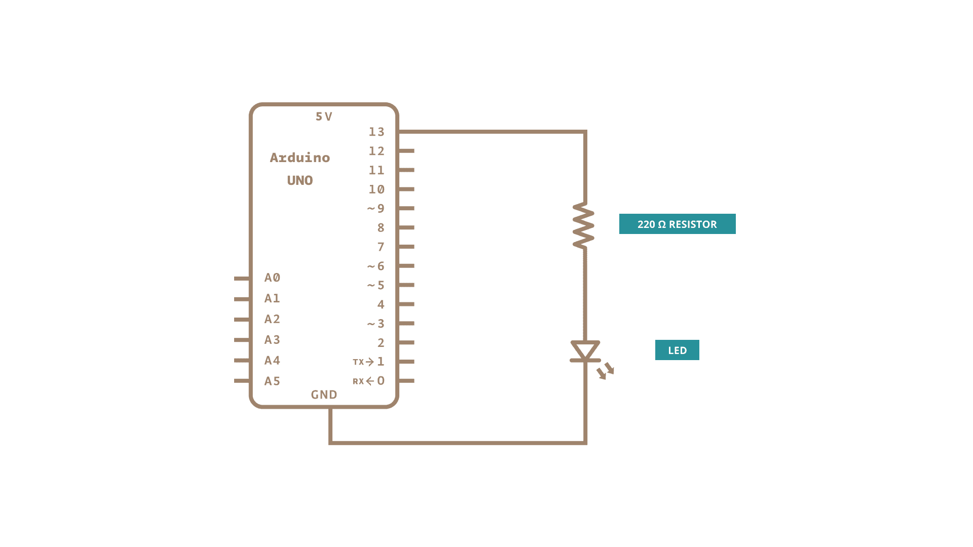
Blinking LED
We desing a ciruit in which the LED will be blinking. It will be bright for one second and dark for one second and the process repeats.
Circuit Diagrams
Code:
int ledPin = 13; // LED on digital pin 13
void setup(){

pinMode(ledPin, OUTPUT); // sets pin 13 as output
}
void loop(){
digitalWrite(ledPin, HIGH); // turns the LED on
delay(1000); // pauses for 1 second
digitalWrite(ledPin, LOW); // turns the LED off
delay(1000); // pauses for 1 second
}
As we can see that the LED blinks with frequency of one second.
Blinking LED with changing brightness
The ciruit diagram in the same but I had connected the LED to pin 9 insted of pin 13.
int ledPin = 9; // LED on digital pin 13
void setup(){

pinMode(ledPin, OUTPUT); // sets pin 13 as output
}
void loop(){
for(i=0;i<256;i++){
analogWrite(ledPin, i);
delay(10)}
for(i=256;i>0;i--){
analogWrite(ledPin, i);
delay(10)}
}
We can see that the LED slowes glows to brighen and then it slowly fades away to be dark.
Measuring DC Voltage
For this we put the one end of the cell to the ground and the other end to analog input pin. This is analog input siutaion. We will use serial output with boudrate $9600$ to display the output.
int pin = A5;
void setup() {
  // put your setup code here, to run once:
  Serial.begin(9600);

}

void loop() {
  // put your main code here, to run repeatedly:
  float val = analogRead(pin);
  Serial.println(val);
  delay(1000);

}
The Voltage was shown to be $3.48V$. This was a small battery cell so that was approximately right.
Stepper Motor control with Arduino
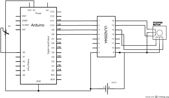
We will connect the stepper motor through a H bridge motor driver. This will help us to direct instruction to the motor. We are using external power supply because the motor take too much power and it is not possible to draw that much power from the arduino board. So the motor driver helps us achieve that too. The Circuit diagram is given below:
 .
.
We are using a full step revolution for the stepper motor. That will require $250$ full steps to achieve $360$ full rotation. There are four magnets in our stepper motor. There would be four pins to control the stepper motor as pin1, pin2, pin3, pin4 We will use the control sequence as pin1-pin3-pin2-pin4. This perticular order of the pins depends on the inner structure of the stepper motor.
The code for linear motion, and simple circular motion is given below.
int pin1= 8;
int pin2 = 9;
int pin3 = 10;
int pin4 = 11;
void setup() {
  // put your setup code here, to run once:
  pinMode(pin1,OUTPUT);
  pinMode(pin2,OUTPUT);
  pinMode(pin3,OUTPUT);
  pinMode(pin4,OUTPUT);

}

void loop() {
for(int i=0;i<200;i++){

  digitalWrite(pin4,HIGH);
  digitalWrite(pin2,LOW);
  digitalWrite(pin3,LOW);
  digitalWrite(pin1,LOW);
  delay(50);

  digitalWrite(pin2,HIGH);
  digitalWrite(pin1,LOW);
  digitalWrite(pin3,LOW);
  digitalWrite(pin4,LOW);
  delay(50);

  digitalWrite(pin3,HIGH);
  digitalWrite(pin2,LOW);
  digitalWrite(pin1,LOW);
  digitalWrite(pin4,LOW);
  delay(50);

  digitalWrite(pin1,HIGH);
  digitalWrite(pin2,LOW);
  digitalWrite(pin3,LOW);
  digitalWrite(pin4,LOW);
  delay(50);}

}
Controlling Circular motion using IR sensor
An infrared proximity sensor or IR Sensor is an electronic device that emits infrared lights to sense some aspect of the surroundings and can be employed to detect the motion of an object. As this is a passive sensor, it can only measure infrared radiation. This sensor is very common in the electronic industry and if you’ve ever tried to design an obstacle avoidance robot or any other proximity detection-based system.
IR sensor is an analog ouput device. It gives a voltage output which is very high when no obsticle in the path. But when an obsticle comes in the path, the output value is very less then. We will put this IR sensor directly beneath the revolution of stepper motor. We have put a check that if the output value is reduced by more than $15$% that would mean that the wire is directly above the sensor and we would stop the motion.
The code for that is given below
int pin1= 8;
int pin2 = 9;
int pin3 = 10;
int pin4 = 11;
int pin = A5;
void setup() {
  Serial.begin(9600);
  // put your setup code here, to run once:
  pinMode(pin1,OUTPUT);
  pinMode(pin2,OUTPUT);
  pinMode(pin3,OUTPUT);
  pinMode(pin4,OUTPUT);

 for(int i=0;i<500;i++){

  float val = analogRead(pin);
  Serial.println(val);

  if(val<250){
    digitalWrite(pin3,LOW);
  digitalWrite(pin2,LOW);
  digitalWrite(pin1,LOW);
  digitalWrite(pin4,LOW);
  break;
    }


  digitalWrite(pin4,HIGH);
  digitalWrite(pin2,LOW);
  digitalWrite(pin3,LOW);
  digitalWrite(pin1,LOW);
  delay(50);

  digitalWrite(pin2,HIGH);
  digitalWrite(pin1,LOW);
  digitalWrite(pin3,LOW);
  digitalWrite(pin4,LOW);
  delay(50);

  digitalWrite(pin3,HIGH);
  digitalWrite(pin2,LOW);
  digitalWrite(pin1,LOW);
  digitalWrite(pin4,LOW);
  delay(50);

  digitalWrite(pin1,HIGH);
  digitalWrite(pin2,LOW);
  digitalWrite(pin3,LOW);
  digitalWrite(pin4,LOW);
  delay(50);}

 }


void loop() {
}
Results:
The stapper motor rotates for given steps of revolution. And when the IR sensor is applied than the stepper motor stops rotating when its above the IR sensor.
Discussion
This was by far the most interesting experiment of the stepper motor. Programming was one of my favorate things from the start of my undergraduate course. And when we see the real things (hardware) being moved by the programming logic, my heart starts dancing with joy. I really enjoyed the experiment. There should be more experiments like this.
Arduino has many many applications in real world. Many things could be automated using arduino. We can make simple things like automated door lock system, PID controlled unlock system. And many more things. It would be a great pleasure for me to learn more about these things.
Arduino can be used to automated observation taking in the labs. For example, in the Debye temperature experiment. We have to take video because there are so many observation that we can’t just write with hand. So in these condition, the knowlege of ardino comes very handy.
